 HighTempPressure
High-Process-Temperature Pressure Sensor Selection Guide
High process temperatures can damage a pressure sensor when the diaphragm, sensing element, cable or electronics exceeds its own limit. Select the thermal path and dynamic response together.
Use temperature bands as a starting point.
| Application target | Thermal route | Measurement check |
|---|---|---|
| Up to 200°C | Qualified direct sensor | Actual media, ambient and compensation ranges |
| 200–450°C process | Fins, standoff, isolation | Heat rejection, lag and offset |
| 450–700°C dry review | Qualified dry sensing head | Thermal packaging and low-frequency cutoff |
| 800–1,500°C+ hot gas | Active water-cooled probe | Exposure, heat load, coolant and usable bandwidth |
Not universal switching thresholds or product ratings. Review the selected configuration.
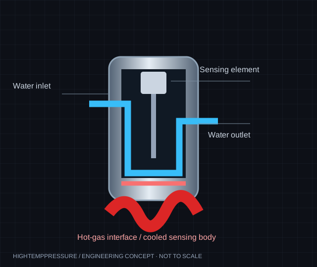
Three temperatures to put on the same RFQ
Record the maximum medium temperature and its duration, the predicted or measured sensing-body temperature, and ambient conditions at electronics and cable terminations. A process gas at 1,200°C does not mean a cooled sensor body is rated for 1,200°C. For a temperature compensated pressure transducer, a compensation range describes characterized error, not necessarily the entire safe operating range.
Up to 200°C: direct sensing may be possible
Some dedicated SOS, SOI or other high-temperature designs support direct sensing, but technology names do not prove a rating. Check the complete datasheet for media and ambient temperature, output type, temperature coefficients and cable limits. Conventional 125°C limits are common design constraints, not a universal silicon failure threshold.
200–450°C process duties: reject or isolate the heat
A finned body, standoff, condensate siphon or remote seal may allow a cooler transmitter to measure a hotter process. Ambient airflow, mounting position, trapped volume, fill-fluid limits and cleaning cycles matter. Remote systems can introduce lag and temperature-induced offset; specify acceptable response.
450–700°C dry duties: select the head and low-frequency behavior
High-temperature charge-mode sensors are a possible route when water is unavailable. SOI and bridge architectures need their own qualified thermal limits. Ask for continuous-versus-transient ratings and the full cable/conditioner arrangement. Charge-mode measurement needs a defined lower cutoff; add a DC-capable channel for long-term mean pressure where necessary.
800–1,500°C+ hot gas: cooling requires a heat-load review
For a water-cooled probe, provide gas temperature, exposure duration and heat-flux information along with flow, inlet temperature, coolant pressure and chiller capacity. There is no universal flow rate or upper gas temperature. Loss-of-flow protection and coolant routing are part of the installation. Extreme transient applications need configuration-specific qualification.
20–200 kHz targets: resonance is not usable bandwidth
A resonant frequency gives a structural response characteristic. Flat measurement bandwidth is a tighter requirement that depends on damping, mounting and the entire signal chain. Specify the highest useful frequency, amplitude/phase tolerance and anti-alias filtering. Sample rate must support that bandwidth with the required filter transition margin; a headline DAQ sample rate alone is insufficient.
Kulite, Kistler, PCB, Druck and ESI: compare a complete model
Reference families may include Kulite WCT/XTE, Kistler 6061B/6041B and PCB 115A/176A, plus Druck or ESI instruments. Use the full part number and released mounting drawing. Check thread form and engagement, seat and seal, probe protrusion, flushness, pressure reference, overload, excitation, charge sensitivity or bridge output, connector wiring and thermal/dynamic limits. Neither a common thread nor a matching range proves drop-in compatibility. Lead time and total price follow a configuration-specific quotation.
Prepare the verification pack before the test
Ask for the selected configuration datasheet, installation/wiring drawings, calibration scope and available thermal/dynamic response evidence. Define acceptance conditions and document any requested customization before ordering. A static calibration certificate alone does not prove hot dynamic response.
Manufacturer references for the selection principles
These explain different sensing approaches. They do not certify HTP configurations.
- Kulite WCTV-312(M): cooled static and dynamic sensing
- Kistler 6041B: water-cooled cylinder pressure measurement
- PCB 176A33: a dry high-temperature approach
- ESI HI2200/2300: model-specific high-temperature data
Sources reviewed 14 November 2026. Third-party names belong to their owners.
Turn your thermal duty into a clear sensor RFQ.
Send media and ambient temperatures, pressure reference, dynamics and mounting requirements.
Request an engineering quote ↗